
 This page is in KOI-8 encoding
 Automated
2D Inversion Basics
The ideas posed by Loke and Barker В основе представленного алгоритма лежат
идеи, опубликованные Локе и Баркером ("Geophysical prospection", 1995)
form the basis of the presented algorithm. Loke's and Barker's "deconvolution"
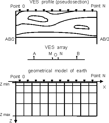
idea is to represent the cross-section under the VES observation line by
a set of 2D blocks with fixed boundaries and certain initial values of
blocks' resisitivity. The theoretical apparent resistivity field is calculated
for the model thus obtained. Then the corrections for the blocks' resisitivities
are estimated by means of the least square method to minimize the difference
between the measured apparent resistivity field and the calculated one.
Loke and Barker apply the finite elements method to estimate the resistivities'
partial derivatives in the least square method and use the expressions
for DC point sources.
The presented algorithm, being ideologically close to Loke's and Barker's
"deconvolution", differs from the latter significantly. The integral equation
method is applied to estimate the partial derivatives in the least square
method. The expressions for the linear current sources are used, i. e.
merely 2D model is considered. The possibility i simplemented to crate
the initial model as thge horizontally layered medium. The class of problems
to solve is thus broadened and additional ways to consider the a priory
information are provided.
TRF_2D for Windows Principal Specifications
The TRF_2D for Windows program processes the traverse of VES with
current line along the observation line.
Three arrays date can be processed:
-
AMNB Schlumberger array (MN<<AB/2) .
-
Amn + mnB half-Schlumberger combined array (MN<<AО).
-
Amn + mnB pole - dipole array (MN<<AО) with fixed current electrode
and moving potential electrodes (dipole); the registration point is attched
to the current electorde position.
Up to 100 sounding points on the observation line.
Up to 20 arbitrary current electrode spasings per sounding point.
The modelled medium is divided into rectangular blocks (up to 1000)
making columns (up to 15 rows of blocks) under each sounding position,
separate column for each sounding point.
The horizontally layered medium can be set as the embedding cross-section.
The inversion results can be presented in the format fitting the SURFER
((c) Golden Software) XYZ data format.
TRF_2D for Windows - Limitations for Usage
Some simplifications adopted to increase the speed of calculation result
naturally in some limitations for usage:
the resistivity contrast cannot exceed 1:10 in the cross-section as
a whole and should not exceed 1:5 for the neighbouring layers of the initial
horizontally-layered medium (if any).
1Alexei A. Bobachev
Dept. of Geophysics, Geological Faculty, MSU
Vorobievy Gory 119899, Moscow, Russia
Phone /fax: (+7-095) 939 49 63
E-mail: boba@geophys.geol.msu.ru
Please feel free to send us
your comments.


